Welding cast iron to steel presents one of the most challenging fabrication tasks facing welders today. These two materials, while both ferrous metals, differ dramatically in their metallurgical properties, carbon content, and thermal behavior. A successful weld requires understanding these differences and applying specialized techniques that prevent cracking, control stress, and produce joints capable of withstanding the demands of industrial applications. Whether you’re repairing heavy machinery, fabricating custom components, or tackling a pipe connection project, mastering this skill opens doors to solutions that many welders consider impossible.
The difficulty in joining these metals stems from their fundamental chemical and physical differences. Cast iron contains significantly more carbon than steel—typically 2-4% versus steel’s 0.02-2%—which radically affects how the material behaves during heating and cooling. When you attempt to weld these metals together without proper technique, you’ll encounter problems ranging from brittle welds to complete joint failure within hours or days of completing the work. However, with the right preparation, filler materials, and welding procedures, you can create strong, durable bonds that perform reliably in demanding environments.
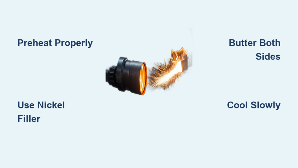
This guide walks you through every aspect of welding cast iron to steel, from understanding why these materials resist bonding to executing techniques that professional fabricators use daily. You’ll learn about preheating protocols, filler metal selection, the buttering method that most experts recommend, and post-weld treatments that ensure your joints hold up over time.
Why Carbon Content Causes Welding Failures Between Cast Iron and Steel
Cast iron’s high carbon content (2-4%) creates immediate challenges when welding to steel (0.02-2%). This carbon imbalance triggers three critical problems that cause most failed welds. First, carbon migration occurs as heat from welding draws carbon atoms from cast iron into the weld pool and steel side, creating brittle hard spots that crack under stress. Second, the graphite flakes in cast iron expand dramatically when heated but can’t contract properly during cooling, generating internal stresses that exceed the material’s strength. Third, cast iron and steel have different thermal expansion rates—cast iron expands about 10% more than steel when heated—which creates shearing forces at the joint interface during temperature changes.
Nickel-based electrodes solve these problems by creating a flexible transition zone. When you use ENiCrFe-3 filler, the nickel content (60-70%) accommodates carbon migration without becoming brittle, while providing enough ductility to absorb the differential expansion between materials. The nickel also forms a microstructure that bonds well with both cast iron’s graphite network and steel’s uniform grain structure. Without this compatible buffer layer, thermal stresses will almost certainly cause cracking within the first thermal cycle after welding.
Critical Preheating Temperatures and Methods for Cast Iron to Steel Joints
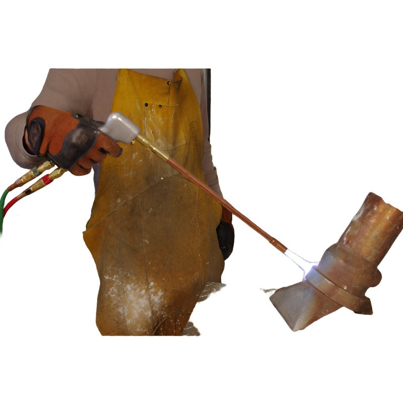
Skipping proper preheating causes 70% of all cast iron welding failures. You must preheat to 500-800°F for gray cast iron or 800-1200°F for ductile cast iron, maintaining these temperatures throughout welding. Use multiple rosebud torch tips to heat large castings evenly, never focusing heat only on the immediate weld area. For components over 1 inch thick, apply heat to a 4-inch radius around the joint to prevent thermal shock.
Monitor temperatures with Tempilstik crayons rather than relying on visual cues—these melt at precise temperatures (500°F, 750°F, etc.) for accurate readings. Maintain interpass temperatures above 400°F for gray iron or 600°F for ductile iron using infrared thermometers between passes. If the metal cools below minimum temperature, reheat slowly to avoid thermal shock. Large castings may require 24 hours of gradual heating to reach target temperature uniformly.
Nickel-Based Filler Selection: ENiCrFe-3 vs. ENiCrFe-2 for Different Applications

Your filler metal choice makes or breaks cast iron to steel welds. ENiCrFe-3 (70% nickel) works best for most repairs requiring maximum crack resistance, especially on thin castings or complex shapes. This high-nickel filler deposits extremely ductile weld metal that accommodates thermal stresses without cracking. Use 1/8-inch diameter rods at 80-100 amps DC reverse polarity for optimal control.
ENiCrFe-2 (55% nickel) offers higher strength for structural applications where the joint faces significant mechanical loads. This filler provides better matching to steel’s strength while maintaining sufficient ductility for cast iron compatibility. It’s ideal for pipe connections, machinery frames, and other load-bearing applications. Avoid steel electrodes completely—they create brittle interfaces that crack during thermal cycling.
Buttering Technique: Creating Reliable Transition Zones Between Dissimilar Metals
The buttering method creates two critical transition zones that prevent direct contact between cast iron and steel. Start by thoroughly cleaning both surfaces to bare metal using a stainless steel grinder wheel—not a wire brush, which imbeds contaminants. Apply the first buttering pass on the cast iron side only, using narrow stringer beads 1/8 inch thick. Keep travel speed slow enough to ensure complete fusion but fast enough to prevent excessive cast iron melting.
After completing the cast iron buttering, apply a matching layer on the steel side, overlapping the cast iron buttering zone by 1/4 inch. This creates a mixed nickel zone that bridges both materials. Each buttering layer should extend 1/2 inch beyond the final weld area. Allow each pass to cool to touch (about 150°F) while maintaining base metal preheat before applying the next pass—this controlled cooling prevents hard spot formation.
Step-by-Step Welding Procedure That Prevents Cracking
With buttering complete, build the final weld in 3/16-inch maximum passes using the same nickel electrode. Maintain a 10-15 degree push angle and travel speed that produces a slightly convex bead profile—concave beads concentrate stress at the weld toe. After each pass cools to 200-250°F (warm but not glowing), lightly peen the weld surface with a rounded hammer to relieve shrinkage stresses.
Critical sequence for successful welding:
1. Maintain preheat temperature throughout the process
2. Use narrow stringer beads rather than wide weaves
3. Allow controlled cooling between passes (never quench)
4. Peen each pass while still warm
5. Clean slag thoroughly before next pass
6. Never exceed 1/4 inch per pass on thick sections
Post-Weld Cooling: The 50°F Per Hour Rule for Crack Prevention
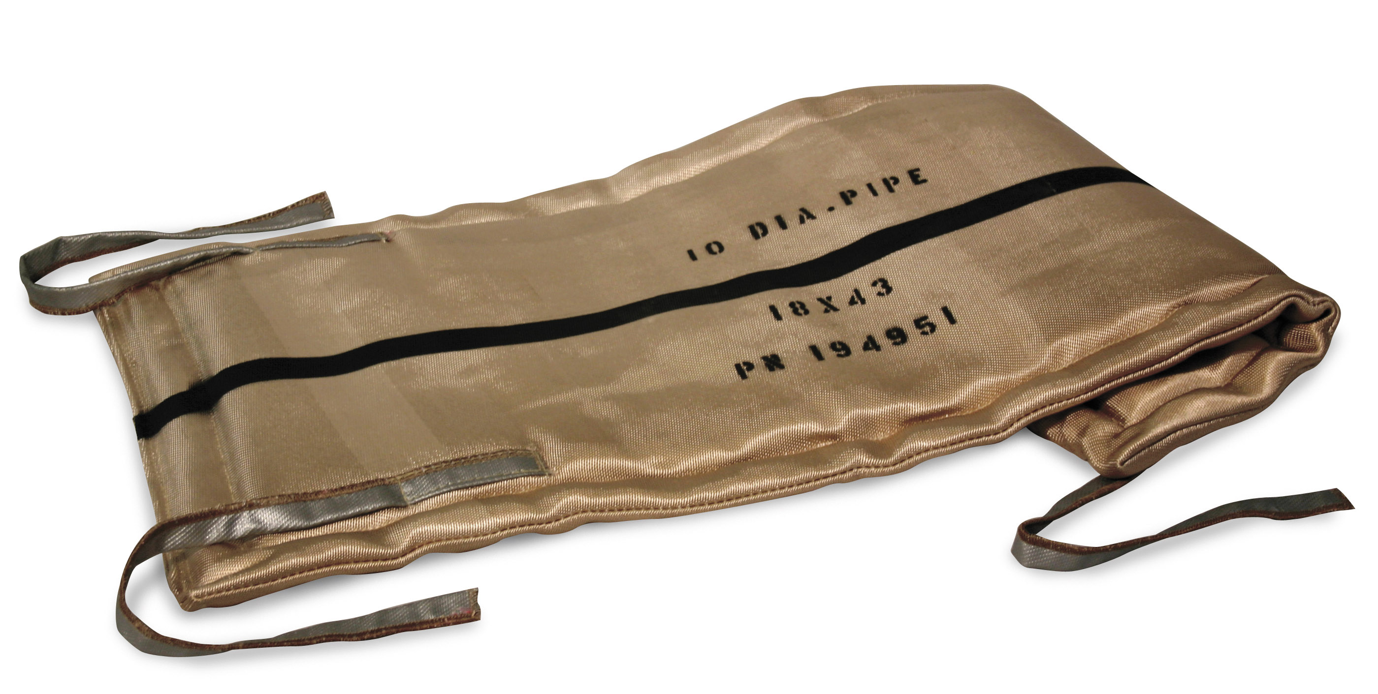
Rapid cooling destroys even perfectly executed welds. After final pass, immediately wrap the entire joint in ceramic fiber insulation blankets or bury in dry sand. The cooling rate must not exceed 50°F per hour for the first 400°F of cooling—faster cooling creates thermal shock that causes cracking. For critical applications, perform full stress relief by heating to 1100°F, holding 1 hour per inch of thickness, then cooling at 50°F/hour.
Check cooling rates with multiple temperature sensors placed at different distances from the weld. If cooling accelerates too quickly, add additional insulation. Leave insulation in place for at least 24 hours for small components or up to 72 hours for large castings. Attempting to rush cooling to return equipment to service faster almost always results in delayed cracking.
Top 3 Mistakes That Cause Immediate Weld Failure
Insufficient preheating remains the #1 cause of failure—welds made without proper preheat typically crack before cooling to room temperature. Using steel electrodes creates brittle interfaces that crack during thermal cycling, even if the initial weld appears sound. Rapid cooling destroys residual stress relief achieved during welding, with most failures occurring within 24-48 hours after welding.
Avoid these mistakes by:
– Preheating entire casting, not just weld zone
– Using nickel-based fillers exclusively
– Implementing controlled cooling with insulation
– Never skipping the buttering step
– Maintaining proper interpass temperatures
Verifying Weld Quality: Beyond Visual Inspection
Visual inspection alone misses 80% of critical defects in cast iron welds. After the weld cools completely, perform magnetic particle testing to detect surface cracks invisible to the naked eye. For critical applications, ultrasonic testing identifies internal porosity or lack of fusion that could cause premature failure.
Check hardness across the weld zone—properly executed welds show gradual transition from cast iron (180-220 HB) through the buttering layer (160-180 HB) to steel (140-160 HB). Sharp hardness jumps indicate improper technique. The ideal weld shows uniform bead appearance with slight convexity and smooth transitions to base metals.
Extending Weld Service Life: Maintenance Protocols for Critical Applications
For machinery operating in thermal cycling environments, apply these maintenance practices:
– Inspect welds monthly for hairline cracks using liquid penetrant
– Keep joint area clean and dry to prevent corrosion
– Avoid thermal shock by gradually heating/cooling equipment
– Apply protective coatings to weld zone in corrosive environments
– Grind weld toes smooth to reduce stress concentration
Welds that undergo regular thermal cycling benefit from periodic stress relief—reheat to 1000°F, hold 30 minutes, then slow cool. This restores ductility lost during service and extends joint life significantly.
Quick Reference: Cast Iron to Steel Welding Checklist
Before welding:
– Clean joint thoroughly to bare metal
– Preheat to 500-1200°F (type-dependent)
– Select proper nickel electrode (ENiCrFe-3 for most repairs)
– Prepare insulation for post-weld cooling
During welding:
– Apply buttering layers to both materials
– Maintain interpass temperature above minimum
– Use narrow stringer beads with controlled heat input
– Peen each pass while warm
After welding:
– Wrap joint in insulation immediately
– Cool at maximum 50°F per hour
– Leave insulation for 24-72 hours
– Perform NDT verification before service
Following these procedures transforms what many consider an impossible task into reliable, long-lasting welds that perform under demanding industrial conditions. The extra time invested in proper preparation and technique pays dividends through reduced repair frequency and extended equipment life.