Cracks in cast iron components like engine blocks, manifolds, and machinery bases often send DIYers and professionals alike searching for solutions. While many assume cast iron is unweldable, successfully welding cast iron with a stick welder is absolutely achievable with the right approach. The key difference from steel welding lies in cast iron’s 2-4% carbon content—significantly higher than mild steel’s 0.08-0.25%—which creates unique challenges requiring specialized techniques. Without proper preparation and procedure, you’ll likely face cracked welds that fail within hours or days of completion.
Most failed cast iron repairs stem from skipping critical steps like adequate preheating or using the wrong electrodes. When you attempt welding cast iron with a stick welder using standard steel electrodes or insufficient heat management, the result is almost always disappointment. The good news? By understanding cast iron’s behavior, selecting proper nickel-based electrodes, and controlling heat throughout the process, you can create strong, lasting repairs that match or exceed the original component’s strength.
This guide cuts through the confusion and provides actionable steps for successful cast iron welding. Whether you’re repairing a cracked engine block or restoring antique machinery, these techniques will transform your approach and results when welding cast iron with a stick welder.
Why Your Cast Iron Welds Keep Cracking
Cast iron’s tendency to crack during welding stems from three fundamental material properties working against you simultaneously. First, the high carbon content (2-4%) creates graphite flakes that become stress concentration points when heated. Second, cast iron has a thermal expansion coefficient of approximately 1.2×10^-5 per degree Celsius—about 1.2 times greater than mild steel—meaning it expands and contracts more dramatically during heating and cooling cycles. Third, cast iron readily absorbs hydrogen from moisture and contaminants, which migrates to stress points and causes delayed cracking hours or days after your weld appears successful.
The most common mistake welders make is treating cast iron like steel. When you apply standard welding techniques to cast iron, rapid cooling transforms carbon in the heat-affected zone into cementite (iron carbide), creating hard, brittle “white iron” zones that crack under thermal stress. This happens because cast iron cools too quickly through the critical 800-400°F range where phase transformations occur. Understanding these mechanisms helps you anticipate problems and implement preventive measures before striking your first arc.
Porosity represents another frequent issue when welding cast iron with a stick welder. Gas evolves from impurities, old oil residues, or moisture trapped in the material’s porous structure, creating voids that compromise weld integrity. Proper cleaning, adequate preheating, and dry electrodes prevent most porosity issues, but neglecting any of these steps introduces defects that undermine your repair.
Select the Right Nickel Electrodes for Cast Iron

Your electrode choice makes or breaks your cast iron repair—standard steel electrodes like E6013 or E7018 will almost certainly fail. Nickel 99 electrodes (ENiCrFe-3 classification) deliver the best results for most cast iron welding applications. These deposit approximately 95% nickel, 3% manganese, and 2% iron, creating weld metal with excellent crack resistance and a thermal expansion coefficient compatible with cast iron. The ductile nature of nickel-based weld metal accommodates the stresses inherent in cast iron repairs without cracking.
For thin sections under 1/4 inch, use 1/16-inch diameter nickel electrodes at 30-50 amps. Components between 1/4 and 1/2 inch thick require 3/32-inch electrodes at 50-80 amps, while heavier sections demand 1/8-inch electrodes at 80-120 amps. Always set your stick welder to DCEN (Direct Current Electrode Negative) polarity for nickel electrodes unless the manufacturer specifies otherwise.
Electrode handling matters as much as selection. Nickel electrodes are hygroscopic—they absorb moisture rapidly from the air. Store them in a dry, heated cabinet at 250-300°F, or bake damp electrodes at 500°F for one to two hours before use. Moisture content above 0.35% introduces hydrogen into the weld, setting up delayed cracking failures. When in doubt about electrode condition, dry them before welding—it’s far cheaper than redoing a failed repair.
Stop Drill Holes and Prepare Cracks Properly
Proper crack preparation prevents propagation during welding and creates a groove that allows complete penetration. Begin by drilling 1/8 to 1/4 inch stop-drill holes at each crack tip—these holes relieve stress at crack ends and prevent further growth. Drill at least 1/2 inch deep or entirely through the crack, whichever comes first.
Next, create a V-groove along the crack’s centerline using a grinding wheel. Include an angle of 60 to 90 degrees with a root face of 1/16 to 1/8 inch and a root opening of about 1/16 inch for optimal penetration. This profile allows the weld to tie into both sides of the joint with complete fusion while minimizing heat input. For thicker sections, consider a U-groove to reduce the total weld metal required.
Thorough cleaning separates successful repairs from failures. Start with mechanical cleaning using a dedicated stainless steel wire brush to remove paint, rust, and scale at least two inches beyond the crack’s visible extent. Follow with chemical cleaning using acetone or MEK to eliminate oils and greases that brushing alone won’t remove. Wipe the cleaned area with lint-free cloths and allow complete evaporation before proceeding—any contamination left behind becomes a potential crack initiation point.
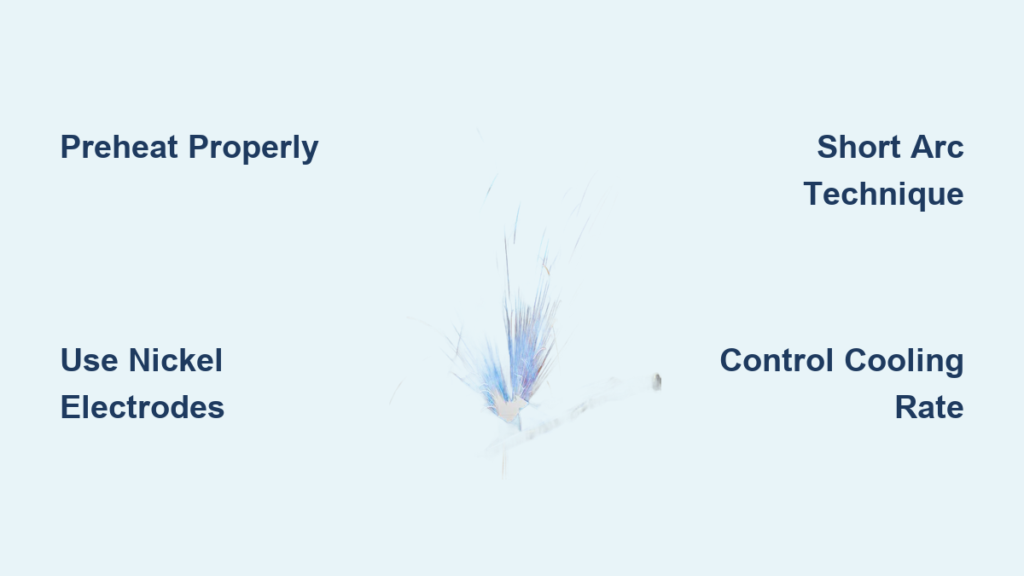
Perfect the Short Arc Welding Technique
Mastering the short arc technique transforms your cast iron welding results. Maintain an arc length of 1/16 to 1/8 inch—significantly shorter than you’d use for steel welding. This short arc minimizes atmospheric contamination of the weld pool and reduces heat input that drives rapid cooling. Hold the electrode at a 45 to 60-degree angle from vertical with a slight drag (10 to 15 degrees back from travel direction).
Limit each bead to 3/4 to 1 inch in length before stopping to clean slag and allow the weld to cool slightly. This prevents heat buildup that could lead to excessive distortion or hard, brittle microstructures. Clean each bead thoroughly before laying the next, as slag inclusions create stress concentration points that promote cracking. For the root pass on thin sections, use the smallest electrode diameter possible (1/16 to 3/32 inch) to minimize heat input.
Peening provides one of the most important techniques for successful cast iron welding. While the weld is still hot (red-orange, approximately 800-1000°F), strike it lightly with a ball-peen hammer, covering the entire bead surface with uniform, overlapping impacts. This mechanical working reduces residual tensile stress and improves crack resistance. Use a light hammer (1-2 ounces for small work) and apply only enough force to deform the surface slightly without cracking the weld metal.
Maintain Critical Temperature Zones During Welding
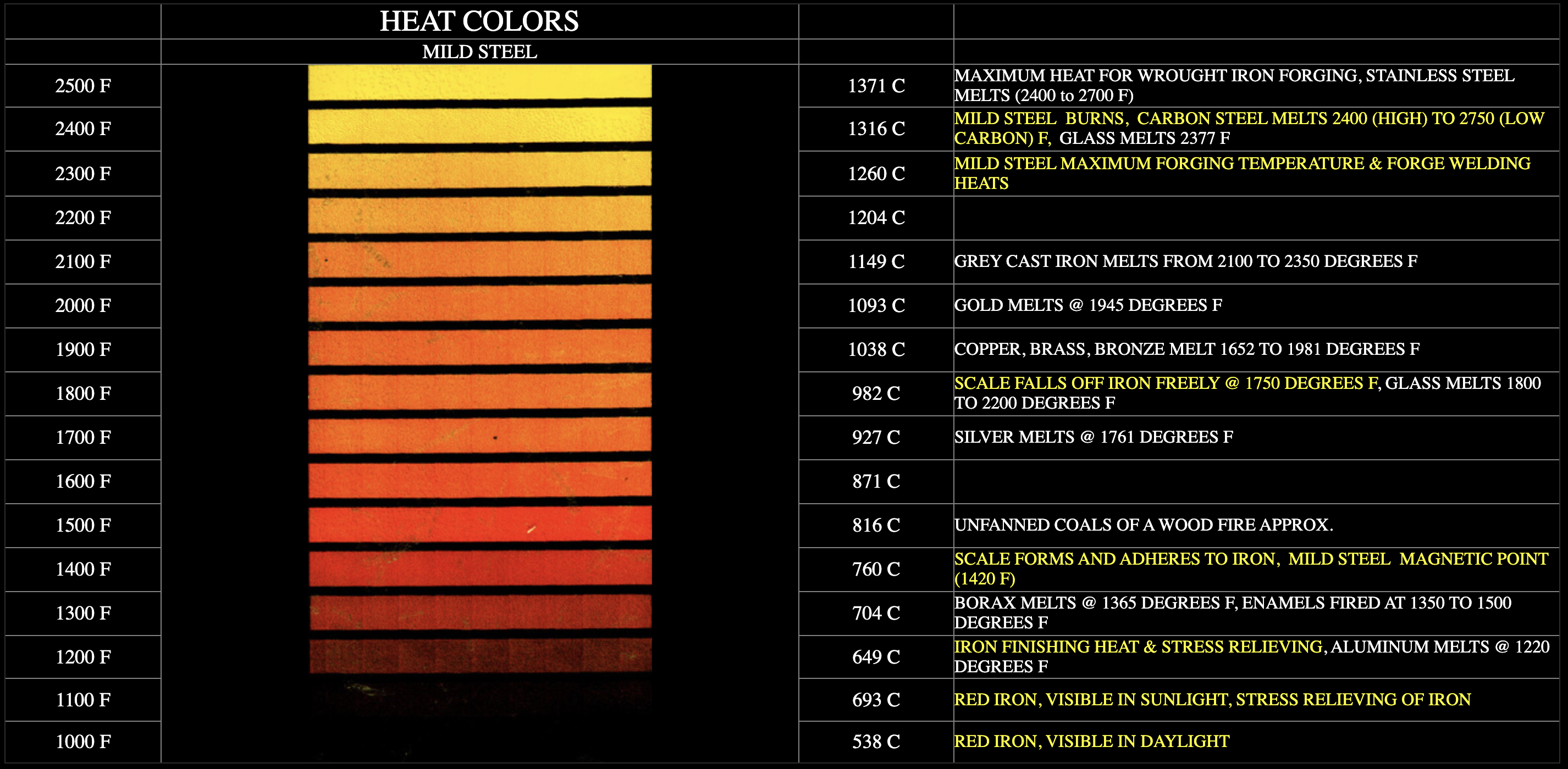
Heat management distinguishes successful cast iron welding from failed attempts. For sections less than 1/4 inch thick, preheat to 300-500°F. Sections from 1/4 to 1/2 inch require 400-600°F, while thicker material needs 500-700°F. Apply heat evenly using an oxygen-acetylene torch, avoiding spot heating that creates temperature gradients. Verify temperature using temperature crayons rated at your target temperature—don’t guess.
Maintain interpass temperature between 300 and 500°F throughout the welding process. Measure at multiple points to ensure uniform heating, especially on large components where temperature gradients can develop. If temperature drops below minimum, pause welding and re-preheat before continuing. Never let the work drop below 300°F between passes unless stopping for an extended period.
Post-weld cooling requires the same attention as heating. Remove the workpiece from heat sources and wrap it immediately in insulation—ceramic fiber blankets, sand, or vermiculite all work effectively. Cool no faster than 100°F per hour below 600°F, with even slower cooling through the critical range of 800-400°F where phase transformations occur. Complete cooling to ambient temperature typically requires 24 hours or more for substantial components. Never quench cast iron or allow rapid cooling—this virtually guarantees cracking.
Fix These Common Cast Iron Welding Failures
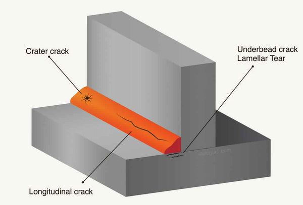
Cracking represents the most common and concerning problem when welding cast iron with a stick welder. Heat-affected zone cracking occurs when rapid cooling creates brittle microstructures—solve by increasing preheat and interpass temperatures. Underbead cracking below the weld surface typically stems from hydrogen contamination, indicating the need for drier electrodes and cleaner base metal. Transverse cracking across the weld bead indicates excessive stress, addressed through peening, smaller beads, and more passes.
Porosity in cast iron welds usually traces to moisture or contamination. Moisture on electrodes produces hydrogen porosity—dry your electrodes more thoroughly. Contaminated base metal creates gas pockets in the weld—return to preparation and clean more aggressively. Rust and scale between passes introduce oxide inclusions—clean each bead completely before laying the next. Oil or grease on the base metal produces carbon porosity—solvent clean until no residue remains on cloths.
Lack of fusion results from insufficient heat, improper electrode angle, excessive travel speed, or cold base metal. Increase amperage by 10-15% if the weld isn’t penetrating properly. Verify your electrode angle is 45-60 degrees with slight drag. Slow your travel speed by 20-30% if you’re moving too fast to achieve fusion. Confirm preheat temperature with crayons rather than estimation.
Protect Yourself from Cast Iron Welding Hazards
Welding cast iron involves specific safety concerns beyond standard welding hazards. Nickel electrodes produce fumes containing nickel compounds that are carcinogenic and can cause sensitization reactions. Work in well-ventilated areas with general ventilation providing 2,000 cfm per welder, or use local exhaust capture within 6-12 inches of the arc that moves 100-150 cfm. For confined spaces or inadequate ventilation, wear NIOSH-approved respiratory protection rated for welding fumes.
Fire safety requires special attention when working on cast iron components that often contain flammable fluids. Clear all combustibles within 35 feet of the welding area. Position a fire watch within range during welding and for 30 minutes after completion. Keep an ABC-rated fire extinguisher within 25 feet. When working on engines or gearboxes, ensure all fuel, oil, and coolant are removed and the component is cleaned of residues that could ignite.
Eye protection must include a welding helmet rated shade 10-12 for stick welding, worn at all times during welding. Add safety glasses beneath the helmet for impact protection when grinding or chipping slag. Hand protection requires heavy leather welding gloves with gauntlet cuffs—extended heating times mean your hands stay closer to the heat source longer than typical steel welding jobs.
Implement These Proven Cast Iron Welding Shortcuts
The preheat step deserves more attention than most welders give it. Invest time in even heating and verifying temperature with temperature crayons rather than estimation. A proper preheat prevents more problems than any other single step—when in doubt, increase your preheat temperature. The additional time spent heating pays dividends in reduced cracking and improved weld quality throughout the repair.
Electrode selection and handling often determine repair success or failure. Keep your nickel electrodes in a dedicated dry storage container, not just in the original package. Test questionable electrodes by striking an arc on a test piece before using them on actual repairs. When electrode cost tempts you to use steel electrodes for non-critical work, resist—steel electrodes on cast iron produce brittle joints that crack, wasting far more time and money than the cost of proper nickel electrodes.
Document your procedures for future reference. Note electrode type and lot number, preheat temperatures, amperage settings, number of passes, and cooling methods. If the repair performs well, you have a proven procedure for similar jobs. If problems develop, documentation helps identify what went wrong and how to prevent recurrence. Start with less critical repairs to build your skills and confidence, then tackle more demanding jobs as your experience grows.