When your automotive exhaust manifold survives repeated thermal cycling or water pipes withstand decades of pressure without failure, you’re witnessing the power of ductile cast iron microstructure at work. This specialized ferrous alloy transforms ordinary cast iron into a material with steel-like strength and ductility through one critical difference: its graphite forms spherical nodules rather than brittle flakes. The resulting microstructure delivers exceptional mechanical properties while maintaining excellent castability for complex shapes. Understanding how this microstructure forms and functions allows engineers to specify precisely the right material for applications ranging from automotive components operating at 800°C to water infrastructure that must perform reliably for generations.
The unique performance of ductile cast iron stems from three interconnected microstructural elements working in concert: the spherical graphite nodules, the metallic matrix surrounding these nodules, and the critical interface between them. Each component can be engineered through alloying and processing to achieve specific mechanical properties. When magnesium is properly added to molten iron (typically 0.02-0.10% residual), it fundamentally alters graphite growth during solidification, creating the spherical nodules that give this material its name and exceptional fracture resistance. Get this microstructure right, and you achieve a material that combines the best properties of steel and cast iron; get it wrong, and you risk premature component failure.
How Magnesium Creates Spherical Graphite Nodules Instead of Flakes

The transformation from flake to nodular graphite represents the defining characteristic of ductile cast iron microstructure, requiring precise magnesium control during melting. Magnesium additions (typically as nickel-magnesium or iron-silicon-magnesium alloys) counteract elements like sulfur, oxygen, titanium, and aluminum that promote flake formation. Any imbalance—too little magnesium or interference from counteracting elements—results in inadequate nodularization and compromised mechanical properties.
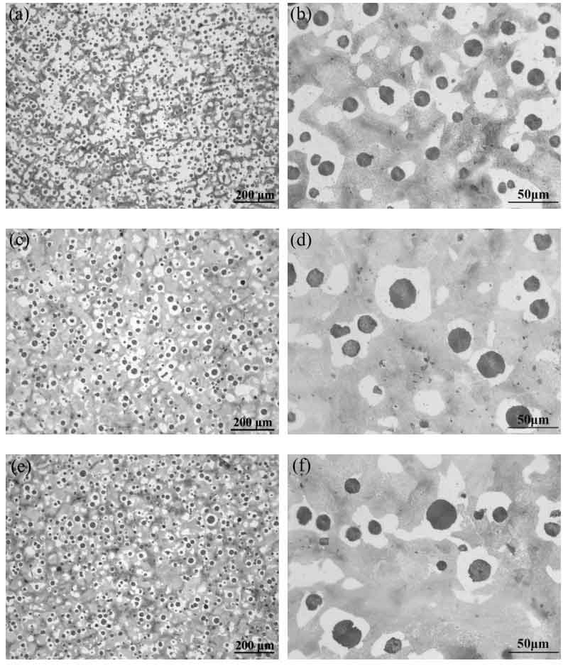
During solidification, austenite dendrites form first, with graphite nodules nucleating in the interdendritic regions. Magnesium segregates to the solid-liquid interface, poisoning growth steps that would otherwise favor flake development. Each nodule develops an austenite shell early in solidification, with carbon diffusion through this shell controlling growth. The effectiveness of this process depends on maintaining sufficient magnesium residual while managing trace elements that interfere with nodularization.
Quality control requires verifying two critical parameters through metallographic analysis:
– Nodularity: Percentage of graphite particles meeting circularity criteria (minimum 80% for true ductile iron)
– Nodule count: Nodules per square millimeter (higher counts generally correlate with improved strength)
What to Check When Nodularity Falls Below 80%
If your ductile iron casting shows poor nodularity, investigate these three common causes:
1. Insufficient magnesium residual – Verify addition rates and account for magnesium loss during pouring
2. Excessive counteracting elements – Test for sulfur, oxygen, titanium, and aluminum in raw materials
3. Extended melt holding time – Magnesium can oxidize or evaporate if molten metal sits too long
Matrix Structures That Transform Mechanical Properties
The metallic matrix surrounding graphite nodules determines key mechanical characteristics and can be engineered through composition and heat treatment. Ferritic matrices (150-200 HB hardness) provide excellent ductility (15%+ elongation) and impact resistance but lower strength (350-450 MPa), making them ideal for water pipes requiring decades of reliable service. When you need higher strength (600-800 MPa) for automotive components, pearlitic matrices deliver through their lamellar ferrite-cementite structure, though with reduced ductility.
Critical Heat Treatment Decisions for Matrix Control
Your choice of heat treatment dramatically alters matrix structure and final properties:
– Annealing (700-750°C with slow cooling): Converts pearlite to ferrite for maximum ductility and machinability
– Normalizing (air cooling from above critical temperature): Refines pearlite structure for improved strength and uniformity
– Austempering (quench to 250-400°C with hold): Creates ausferritic structure combining high strength (>1200 MPa) with useful ductility for gears and suspension components
SiMo Alloys: Microstructure Solutions for 800°C Operating Temperatures
Silicon-molybdenum (SiMo) ductile cast irons solve the critical problem of elevated temperature softening that plagues conventional grades. The 3.5-4.5% silicon content provides triple functionality: promoting graphite stability, forming protective oxide layers for oxidation resistance, and delivering solid solution strengthening that persists at high temperatures. When you’re designing components for exhaust manifolds or turbocharger housings, these silicon benefits become essential.
Molybdenum (0.5-1.5%) transforms high-temperature performance through three mechanisms:
– Solid solution strengthening that remains effective at elevated temperatures
– Retarding austenite-to-pearlite transformation for thermal cycling stability
– Forming fine carbide precipitates that inhibit grain growth and provide additional strengthening
Why SiMo Alloys Outperform Conventional Ductile Iron at 800°C
At 800°C service temperatures, conventional ductile iron experiences significant softening from pearlite decomposition and reduced strengthening effectiveness. Meanwhile, properly formulated SiMo alloys maintain tensile strength in the 100-150 MPa range through:
– Persistent solid solution strengthening from silicon, molybdenum, and niobium
– Precipitation hardening from stable carbides and carbonitrides
– Intrinsic stability of graphite nodules that neither dissolve nor transform
This combination enables reliable performance in automotive exhaust applications where conventional materials would fail.
Niobium: The Cost-Effective Alternative to Molybdenum in High-Temperature Alloys

When material costs become critical but performance can’t be compromised, niobium substitution offers a strategic solution for SiMo ductile iron production. Adding 0.05-0.30% niobium forms stable carbides and carbonitrides that provide precipitation strengthening similar to molybdenum at elevated temperatures. The smaller atomic size of niobium creates greater lattice strain per atom, potentially delivering enhanced solid solution strengthening with less total addition.
Critical Verification Steps for Niobium-Modified Alloys
Before switching to niobium-containing formulations, confirm these three microstructural characteristics:
1. Graphite nodularity remains above 80% – Niobium shouldn’t compromise the essential spherical morphology
2. Carbide distribution matches specifications – Verify through optical microscopy that niobium carbides appear as fine, discrete particles
3. Elevated temperature properties meet requirements – Conduct comparative testing at 800°C to ensure strength retention
Research shows niobium additions don’t significantly alter graphite nodularity when magnesium content remains sufficient for complete nodularization during solidification.
Essential Microstructural Analysis Techniques for Quality Control
Verifying ductile cast iron microstructure requires systematic metallographic examination following standardized procedures. Your metallography lab should implement this three-step verification process:
Step 1: Optical Microscopy for Routine Quality Control
- Prepare samples through sectioning, mounting, grinding, and polishing
- Etch with Nital (1-5% nitric acid in alcohol) to reveal matrix structure
- Quantify graphite nodularity per ASTM E2567 or ISO 16112 standards
- Measure nodule count (nodules/mm²) as an additional quality metric
Step 2: Advanced Characterization for Problem Solving
When troubleshooting performance issues, escalate to:
– Scanning electron microscopy (SEM): Analyze carbide morphology and elemental distribution via energy-dispersive X-ray spectroscopy
– Transmission electron microscopy (TEM): Examine atomic-scale carbide structures and graphite-matrix interfaces (though sample preparation presents challenges)
Common Microstructural Defects and Their Impact
Watch for these critical defects during examination:
– Poor nodularity (<80%): Causes significantly reduced ductility and impact resistance
– Carbide networks along grain boundaries: Creates preferential fracture paths
– Graphite flotation: Results from excessive carbon content or slow cooling rates
Heat Treatment Secrets for Optimizing Ductile Iron Performance
Your heat treatment selection directly controls the final matrix structure and mechanical properties. For components requiring maximum strength-to-weight ratio, austempering creates ausferritic microstructures combining acicular ferrite with retained austenite. This process involves full austenitization followed by quenching to 250-400°C and holding until transformation completes—producing mechanical properties that can exceed quenched and tempered steels.
Time-Saving Heat Treatment Shortcuts
When production schedules tighten, consider these validated approaches:
– Direct austempering of as-cast parts: Eliminates separate austenitizing step for suitable geometries
– Controlled cooling rates: Achieve target matrix structures without full heat treatment for less critical applications
– Selective hardening: Apply localized heat treatment only to high-wear areas, saving energy and time
Quality Control Checklist for Reliable Ductile Iron Production
Preventing microstructural defects requires rigorous control of chemical composition throughout production. Your quality system must monitor:
Critical Composition Parameters
- Carbon (3.4-3.8%): Must balance adequate graphite formation against flotation risk
- Silicon (2.2-4.5%): Controls graphitization and provides solid solution strengthening
- Magnesium (0.02-0.10% residual): Narrow window ensures nodularization without excessive dross
Mechanical Verification Protocol
- Tensile testing per ASTM A370/ISO 6892: Primary verification of strength and ductility
- Hardness testing: Rapid quality control correlating to strength (use grade-specific calibration)
- Charpy impact testing: Essential for applications involving shock loading or low temperatures
When your ductile cast iron microstructure meets specifications, you achieve the optimal balance of strength, ductility, and castability that makes this material indispensable for critical engineering applications. By understanding how graphite morphology, matrix structure, and alloying elements interact, you can confidently select and specify ductile iron for even the most demanding service conditions. The ongoing development of niobium-modified alloys and advanced processing techniques promises to further extend the capabilities of this versatile material, ensuring its continued relevance in next-generation engineering designs.